
Defining port settings

You can define typical port settings for a specific I/O adapter type by creating a port pattern.

About this task

You can use network settings in port patterns to configure switch internal ports. However, you cannot use port patterns to configure the switch global settings, such as VLAN IDs, global UFP mode, global CEE mode, and global FIPs. You must manually configure the global settings using the following rules that are compatible with the internal port settings that you intend to deploy before you deploy the port patterns. You also cannot use port patterns to configure the PVID tagging. See the documentation that came with your switch to determine the compatibility checks between the global settings and internal port settings and how to configure these settings for that switch.
  • Ensure that globalCEEState is On when PFC is configured.
  • Ensure that globalCEEState is On when vport is set to FCoE mode.
  • Ensure that globalCEEState is On and globalFIPsState is On when FIPs are configured.
  • Ensure that globalUFPMode is Enable when the switch internal port mode is set to UFP mode.
  • Ensure that the VLAN ID is created before adding a port to a specific VLAN.

Procedure

Complete the following steps to create an I/O adapter port pattern.

  1. From the Lenovo XClarity Administrator menu bar, click Provisioning > Patterns. The Configuration Patterns: Patterns page is displayed.
  2. Click the Category Patterns tab.
  3. Click the Port Pattern vertical tab, and then click the Create icon (Create icon).
    Add I/O Adapter
    You can also create a new port pattern from the page by clicking the Create icon (Create icon) next to the Initial port pattern selection.
  4. In the New Port Pattern dialog, specify the following information.
    • Enter a name and description for the pattern.

    • Specify the following adapter and port compatibility settings. When assigning patterns to adapters and ports, pattern settings are filtered based on compatibility with the target adapter or port.

      • Target adapter type
      • Target port operational mode, including:
        • pNIC mode
        • vNIC virtual fabric mode
        • vNIC switch independent mode
        • vNIC unified fabric protocol mode

        These settings enable NIC virtualization. For more information, see NIC Virtualization in Flex System Fabric Solutions.

      • Target port protocols, including:
        • Ethernet only

        • Ethernet and FCoE

        • Ethernet and iSCSI

      • Port extended settings pattern, which is used to configure additional port settings that are learned from the server
    • If you set the target port operational mode to pNIC mode, choose to apply corresponding settings to the Flex switch internal ports, where applicable. If selected, you can configure additional VLAN and advanced settings:

      • Specify the target port protocol.
      • If you set the target port protocol to Ethernet and FCoE, optionally select and specify the priority 2 ID.
    • If you set the target port operational mode to vNIC virtual fabric mode, configure the physical function settings, including the type and VLAN tag for each function.

    • If you set the target port operational mode to vNIC switch independent mode, specify the type, minimum bandwidth and VLAN tag for each enabled function. You can also choose to apply corresponding settings to the Flex switch internal ports, where applicable. If selected, you can configure additional switch internal port and advanced settings:
      • Specify the default LAN, which is used only by the operating system when the operating system sends untagged packets.
      • Specify a comma separated list of VLANs.
      • Choose to configure manual control and specify the triggers.
      • Choose to configure flow control type, including
        • Keep existing flow control
        • Priority-based flow control
        • Link-level flow control

        For more information about these flow-control types, see the documentation that came with your Flex switch.

    • If you set the target port operational mode to vNIC unified fabric protocol mode, choose to apply corresponding settings to the Flex switch internal ports, where applicable. If selected, you can configure additional UFP function and advanced settings:

      • Specify the QoS Mode (bandwidth or priority).

      • Choose to enable default VLAN ID tagging and specify the mode, minimum bandwidth and VLAN tag for each enabled function.

      • Choose to configure layer 2 failure and specify the number of triggers for each function.

      • For bandwidth QoS mode, specify the flow control type (priority based, link-level, or existing flow control).

      • For bandwidth QoS mode, choose to whether priority 4 is enabled when iSCSI is selected.

      Note
      Ensure that global failover is On when defining failover triggers.
  5. Click Create.

Results

The new pattern is listed on the Port Patterns tab in the Configuration Patterns: Category Patterns page:
Illustrates the list of customized ports patterns on the Configuration Patterns: Category Patterns page.
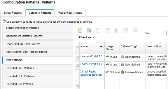
From this page, you can also perform the following actions on a selected category pattern:
  • Modifying current pattern settings by clicking the Edit icon (Edit icon).
  • Copy an existing pattern by clicking the Copy icon (Edit icon).
  • Delete a pattern by clicking the Delete icon (Delete icon).
  • Rename a pattern by clicking the Rename icon (Rename icon).
  • Import or export patterns (see Exporting and importing server and category patterns).