
Configuring network access

When you initially set up Lenovo XClarity Administrator, you configure up to two network interfaces. In addition, you must specify which of those interfaces is to be used to deploy operating systems. After the initial setup, you can modify these settings.

Before you begin

Attention
  • Changing the XClarity Administrator IP address after managing devices might cause the devices to be placed in offline state in XClarity Administrator. Ensure that all devices are unmanaged before changing the IP address.
  • You can enable or disable checking for duplicate IP addresses in the same subnet by clicking the Duplicate IP address checking toggle. It is disabled by default. When enabled, XClarity Administrator raises an alert if you attempt to change the IP address of XClarity Administrator or manage a device that has the same IP address as another device that is under management or another device found in the same subnet.
    Note
    When enabled, XClarity Administrator runs an ARP scan to find active IPv4 devices on the same subnet. To prevent the ARP scan, disable Duplicate IP address checking.
  • When running XClarity Administrator as a virtual appliance, if the network interface for the management network is configured to use the Dynamic Host Configuration Protocol (DHCP), the management-interface IP address might change when the DHCP lease expires. If the IP address changes, you must unmanage the chassis, rack and tower servers, and then manage them again. To avoid this problem, either change the management interface to a static IP address, or ensure that the DHCP server configuration is set so that the DHCP address is based on a MAC address or that the DHCP lease does not expire.
  • If you do not intend to use XClarity Administrator to deploy operating system or update OS device drivers, you can disable Samba and Apache servers by changing the network interface to use the discover and manage hardware only option. Note that the management server is restarted after changing the network interface.
  • When running XClarity Administrator as a container, ensure that a macvlan network is set up on the host system..

About this task

XClarity Administrator has two separate network interfaces that can be defined for your environment, depending on the network topology that you implement. For virtual appliances, these networks are named eth0 and eth1. For containers, you can choose custom names.
  • When only one network interface (eth0) is present:
    • The interface must be configured to support the device discovery and management (such as server configuration and firmware updates). It must be able to communicate with the CMMs and Flex switches in each managed chassis, the baseboard management controller in each managed server, and each RackSwitch switch.
    • If you intend to acquire firmware and OS device-driver updates using XClarity Administrator, at least one of the network interfaces must be connected to the Internet, preferably through a firewall. Otherwise, you must import updates into the repository.
    • If you intend to collect service data or use automatic problem notification (including Call Home and Lenovo Upload Facility), at least one of the network interfaces must be connected to the Internet, preferably through a firewall.
    • If you intend to deploy operating-system images and update OS device drivers, the interface must have IP network connectivity to the server network interface that is used to access the host operating system.
      Note
      If you implemented a separate network for OS deployment and OS device-driver updates, you can configure the second network interface to connect to that network instead of the data network. However, if the operating system on each server does not have access to the data network, configure an additional interface on the servers to provide connectivity from the host operating system to the data network for OS deployment and OS device-driver updates, if needed.
  • When two network interfaces (eth0 and eth1) are present:
    • The first network interface (typically the Eth0 interface) must be connected to the management network and configured to support the device discovery and management (including server configuration and firmware updates. It must be able to communicate with the CMMs and Flex switches in each managed chassis, the management controller in each managed server, and each RackSwitch switch.
    • The second network interface (typically the eth1 interface) can be configured to communicate with an internal data network, a public data network, or both.
    • If you intend to acquire firmware and OS device-driver updates using XClarity Administrator, at least one of the network interfaces must be connected to the Internet, preferably through a firewall. Otherwise, you must import updates into the repository.
    • If you intend to collect service data or use automatic problem notification (including Call Home and Lenovo Upload Facility), at least one of the network interfaces must be connected to the Internet, preferably through a firewall.
    • If you intend to deploy operating-system images and update OS device drivers, you can choose to use either eth1 or eth0 interface. However, the interface that you use must have IP network connectivity to the server network interface that is used to access the host operating system.
      Note
      If you implemented a separate network for OS deployment and OS device-driver updates, you can configure the second network interface to connect to that network instead of the data network. However, if the operating system on each server does not have access to the data network, configure an additional interface on the servers to provide connectivity from the host operating system to the data network for OS deployment and OS device-driver updates, if needed.
The following table shows possible configurations for the XClarity Administrator network interfaces based on the type of network topology that has been implemented in your environment. Use this table to determine how to define each network interface.
Table 1. Role of each network interface based on network topology
Network topologyRole of interface 1 (eth0)Role of interface 2 (eth1)
Converged network (management and data network with support for OS deployment and OS device-driver updates)Management network
  • Discovery and management
  • Server configuration
  • Firmware updates
  • Service data collection
  • Automatic problem notification (such as Call Home and Lenovo Update Facility)
  • Warranty data retrieval
  • OS deployment
  • OS device-driver updates
None
Separate management network with support for OS deployment and OS device-driver updates and data networkManagement network
  • Discovery and management
  • Server configuration
  • Firmware updates
  • Service data collection
  • Automatic problem notification (such as Call Home and Lenovo Update Facility)
  • Warranty data retrieval
  • OS deployment
  • OS device-driver updates
Data network
  • None
Separate management network and data network with support for OS deployment and OS device-driver updatesManagement network
  • Discovery and management
  • Server configuration
  • Firmware updates
  • Service data collection
  • Automatic problem notification (such as Call Home and Lenovo Update Facility)
  • Warranty data retrieval
Data network
  • OS deployment
  • OS device-driver updates
Separate management network and data network without support for OS deployment and OS device-driver updatesManagement network
  • Discovery and management
  • Server configuration
  • Firmware updates
  • Service data collection
  • Automatic problem notification (such as Call Home and Lenovo Update Facility)
  • Warranty data retrieval
Data network
  • None
Management network only (OS deployment and OS device-driver updates is not supported)Management network
  • Discovery and management
  • Server configuration
  • Firmware updates
  • Service data collection
  • Automatic problem notification (such as Call Home and Lenovo Update Facility)
  • Warranty data retrieval
None

For more information about XClarity Administrator network interfaces including IPv6 address limitations, see Network considerations.

Procedure

To configure network access, complete the following steps.

  1. From the XClarity Administrator menu bar, click Administration > Network Access. The current network settings are displayed.
  2. Optionally enable checking for duplicate IP addresses in the same subnet by clicking the Duplicate IP address checking toggle.

    When enabled, XClarity Administrator raises an alert if you attempt to change the IP address of XClarity Administrator or manage a device that has the same IP address as another device that is under management or another device found in the same subnet.

  3. Click Edit Network Access to display the Edit Network Access page.

    Illustrates the Edit Network Access page.
  4. If you intend to deploy operating-systems and update OS device drivers using XClarity Administrator, choose the network interface to use for managing operating systems.
    • If only one interface is defined for XClarity Administrator, choose whether that interface is to be used to discover and manage hardware only, or whether it is also to be used to manage operating systems.

    • If two interfaces are defined for XClarity Administrator (Eth0 and Eth1), determine which interface is to be used to manage operating systems. If you choose None, you cannot deploy operating-system images or update OS device drivers to managed servers from XClarity Administrator.

  5. (XClarity Administrator as a virtual appliance only) Modify the IP Settings.
    1. For the first interface, specify the IPv4 address, IPv6 address, or both.
      • IPv4. You must assign an IPv4 address to the interface. You can choose to use a statically assigned IP address or obtain an IP address from a DHCP server.
      • IPv6. Optionally, you can assign an IPv6 address to the interface using one of the following assignment methods:
        • Use statically assigned IP address
        • Use stateful address configuration (DHCPv6)
        • Use stateless address auto configuration
        Note
        For information about IPv6 address limitations, see IP configuration limitations.
    2. If a second interface is available, specify the IPv4 address, the IPv6 address, or both.
      Note
      The IP addresses that are assigned to this interface must be in a different subnet from the IP addresses that are assigned to the first interface. If you choose to use DHCP to assign IP addresses for both interfaces (Eth0 and Eth1), the DHCP server must not assign the same subnet for the IP addresses of the two interfaces.
      • IPv4. You can choose to use a statically assigned IP address or obtain an IP address from a DHCP server.
      • IPv6. Optionally, you can assign an IPv6 address to the interface using one of the following assignment methods:
        • Use statically assigned IP address
        • Use stateful address configuration (DHCPv6)
        • Use stateless address auto configuration
    3. Specify the default gateway.

      If you specify a default gateway, it must be a valid IP address and must use the same network mask (the same subnet) as the IP address for one of the network interfaces (Eth0 or Eth1). If you use a single interface, default gateway must be on the same subnet as network interface.

      If either interface uses DHCP to obtain an IP address, the default gateway also uses DHCP. To manually input a default gateway address that overrides the one received from DHCP server, select the Override Gateway checkbox.

      Tip
      • Ensure that the gateway matches one of the network interfaces' subnet. The default gateway is automatically set through that network interface.

      • To go back to a DHCP-provided gateway, clear the Override Gateway checkbox.

      CAUTION
      If you choose to override the gateway, take care to input the correct gateway address; otherwise, this management server will be unreachable and there would be no way to remotely login to correct it.
    4. Click Save IP Settings.
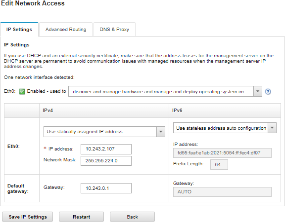
  6. (XClarity Administrator as a virtual appliance only) Optionally, modify the advanced settings.
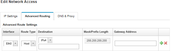
    1. Click the Advanced Routing tab.

      Illustrates the Edit Network Access page.
    2. Specify one or more route entries in the Advanced Route Settings table to be used by this interface.
      To define one or more route entries, complete the following steps.
      1. Choose the interface.
      2. Specify the route type, which can be a route to another host or to a network.
      3. Specify the destination host or network address to which you are directing the route.
      4. Specify the subnet mask for the destination address.
      5. Specify the gateway address to which packets are to be addressed.
    3. Click Save Advanced Routing.
  7. Optionally, modify the DNS and proxy settings.

    When XClarity Administrator is setup as a container, only proxy settings can be modified form the web interface. The DNS settings are defined in the container.

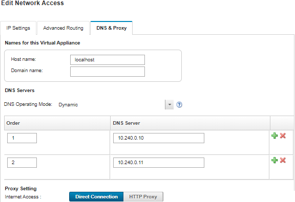
    1. Click the DNS & Proxy tab.

      Illustrates the Edit Network Access page.
    2. Specify the hostname and domain name to be used for XClarity Administrator.
    3. Select the DNS operating mode. This can be Static or DHCP.
      Attention
      You must restart the management server when you change the DNS operating mode.
      Note
      If you choose to use a DHCP server to obtain the IP address, any changes that you make to the DNS Server fields are overwritten the next time XClarity Administrator renews the DHCP lease.
    4. Specify the IP address of one or more Domain Name System (DNS) servers to be used, and the priority order for each.
    5. Specify whether to access the Internet using a direct connection or an HTTP proxy (if XClarity Administrator has access to the Internet).
      Note
      If using a HTTP proxy, ensure that the following requirements are met.
      • Ensure that the proxy server is set up to use basic authentication.

      • Ensure that the proxy server is set up as a non-terminating proxy.

      • Ensure that the proxy server is set up as a forwarding proxy.

      • Ensure that load balancers are configured to keep sessions with one proxy server and not switch between them.

      If you choose to use an HTTP proxy, complete the required fields:

      1. Specify the proxy server hostname and port.

      2. Choose whether to use authentication, and specify the user name and password if required.

      3. Specify the proxy test URL.

      4. Click Text Proxy to verify that the proxy settings are configured and working correctly.

    6. Click Save DNS & Proxy.
    7. Optional: Push the XClarity Administrator management server fully-qualified domain name (FQDN) and DNS information to managed servers with IMM2, XCC, and XCC2 so that the managed servers can find the management server using this information.
      1. Click Push FQDN / DNS to BMC.

      2. Choose how to handle existing DNS entries in the baseboard management controller.

        • Keep the existing DNS entries, and append the management server DNS entries in the next available slot.

        • Replace all existing DNS entries with the management server DNS entries.

      3. Type YES in the edit field.

      4. Click Apply.

      A job is created to perform this operation. You can monitor the progress of the job from the Monitoring > Jobs card. If the job did not complete successfully, click the job link to display details about the job (see Working with jobs .)

      You can also remove the management server FQDN and DNS information from managed servers with IMM2, XCC, and XCC2 by clicking Remove FQDN / DNS from BMC. You can choose to keep other existing DNS entries, remove all DNS entries, or remove only entries that match the management server information.

  8. Click Restart to restart the management server.
  9. Click Test Connection to verify the network settings.