Defining I/O adapters
You can define I/O port settings and addressing mode to be applied to target servers when this pattern is deployed.
About this task
If you intend to virtualize or reassign your I/O adapter addresses, you can configure this pattern to use virtual I/O adapter addressing.
If you are creating a pattern from an existing server, some adapter information might be automatically learned. You can define additional I/O adapter patterns to match the hardware that you expect to have in the servers when this pattern is deployed. By defining I/O adapter patterns, you can configure adapter-port settings for your supported adapter. If using virtual I/O adapter addresses, you can also define SAN boot targets for Fibre Channel adapters that you add (see Defining boot options).
Procedure
To define I/O adapter settings, complete the following steps.
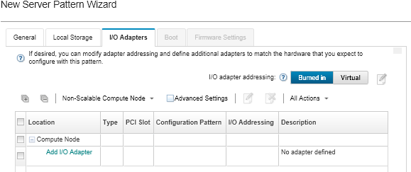
- From the New Server Pattern Wizard, click the I/O Adapters tab.
 NoteYou can display additional information about the I/O adapters by clicking
Advanced Settings. - If you are creating a server pattern for a server in a Flex System chassis, choose the type of I/O-adapter addressing mode:
Burned in. Use existing World Wide Name (WWN) and Media Access Control (MAC) addresses that are provided with the adapter from manufacturing.
Virtual. Use virtual I/O adapter addressing to simplify the management of LAN and SAN connections. Virtualizing I/O-addresses reassigns the burned-in hardware addresses with virtualized Fibre WWN and Ethernet MAC addresses. This can speed deployment by pre-configuring SAN zone membership and facilitate failover by eliminating the need to reconfigure SAN-zoning and LUN-masking assignments when replacing hardware.
When virtual addressing is enabled, both Ethernet and Fibre Channel addresses are allocated by default regardless of defined adapters. You can choose the pool from which Ethernet and Fibre Channel addresses are allocated.
You can also edit virtual-address settings by clicking the Edit icon (
 ) next to the address modes.Restriction: Virtual addressing is supported for only servers in Flex System chassis. Rack and tower servers are not supported.
- Choose the I/O adapters that you expect to be installed in the servers to which the pattern is to be deployed. To add an adapter:
- Select the initial port pattern to be assigned to all ports in the port group when the pattern is deployed.
Port patterns are used to modify port settings that are learned from the server. These initial port patterns are assigned when the adapter is first added. After the adapter is added, you can assign different patterns to individual ports from the I/O Adapter page.
You can create a port pattern by clicking the Create icon (
 ). You can create a port pattern based on an existing pattern by clicking the Edit icon ().
For more information about port patterns, see Defining port settings.
- Select the initial port pattern to be assigned to all ports in the port group when the pattern is deployed.