Step 1: Cable the chassis, rack servers, and Lenovo XClarity Administrator host to the top-of-rack switches
Cable the chassis, rack servers, and XClarity Administrator host to the top-of-rack switches to enable communications between the devices and your networks.
Procedure
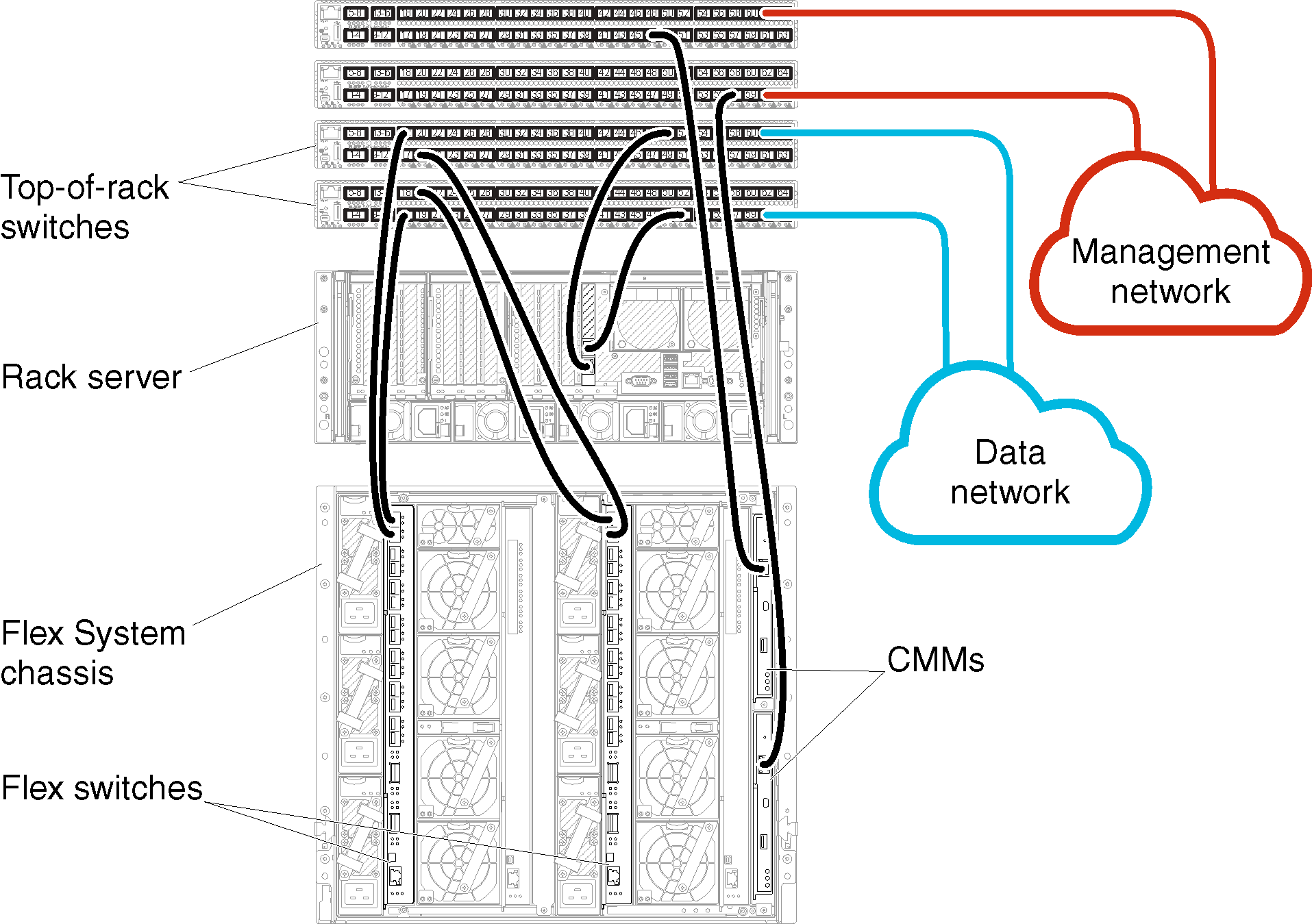
Cable each Flex switch and CMM in each chassis, each rack server, and the XClarity Administrator host to both top-of-rack switches. You can choose any ports in the top-of-rack switches.
The following figure is an example that illustrates cabling from the chassis (Flex switches and CMMs), rack servers, and XClarity Administrator host to the top-of-rack switches.
Note
This figure does not depict all cabling options that might be required for your environment. Instead, this figure shows only the cabling-option requirements for the Flex switches, CMMs, and rack servers as they relate to setting up physically separate data and management networks.
Tip
Instead of setting up two physical switches that are connected to each network for redundancy (for a total of four switches), you can set up a single physical switch that is connected to each network (for a total of two switches). In that case, each switch would be connected to both networks, and you would implement two VLANs: one for the data network and one for the management network, to segregate data traffic.
Figure 1. Example cabling for physically separate data and management networks
Give feedback