Ensure that all appropriate ports are enabled, including external ports from the Flex switch to the top-of-rack switch and internal ports to the CMM.
You can implement VLAN tagging in the Flex switches or top-of-rack switches, depending on the needs and complexity of your environment. If you implement tagging from the Flex switches, enable VLAN tagging from the Flex switches.
Ensure that VLAN IDs are set up for the management and data networks.
Important
For each Flex System chassis, ensure that the fabric type of the expansion card in each server in the chassis is compatible with the fabric type of all Flex switches in the same chassis. For example, if Ethernet switches are installed in a chassis, all servers in that chassis must have Ethernet connectivity through the LAN-on-motherboard connector or an Ethernet expansion card. For more information about configuring Flex switches, see Configuring I/O modules in the Flex Systems online documentation.
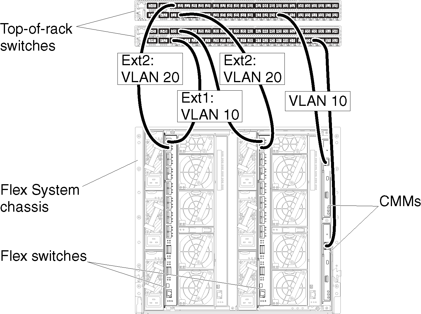
The following figure is an example scenario that illustrates VLAN tagging that is implemented in the Flex switches and enabled on the management and data networks. The management VLAN is set up as VLAN 10 (Ext1), and the data VLAN is set up as VLAN 20 (Ext2).
Figure 1. Example configuration for Flex switches on virtually separate data and management networks (Red Hat KVM) in which VLAN tagging is enabled on both networks
Complete the following steps to configure the Flex switches for this scenario:
Configure the Flex switch in Flex switch bay 1:
Define the management VLAN (in the example, we chose VLAN 10) to contain the external port where the cable is routed to the top-of-rack management switch (Ext1).
Assign a virtual Network Interface Card (vNIC) function from the compute node on which Lenovo XClarity Administrator is installed to the management VLAN (VLAN 10). The following table provides information about how vNICs on the compute node are mapped on the Flex switch:
Table 1. Correlation between vNIC IDs and PCIe functions on the servers
PCIe Function (UEFI)
Compute node physical port
Flex switch bay
vNIC ID
0
0
1
x.1 (7.1 in this example)
2
x.2 (7.2 in this example)
4
x.3 (7.3 in this example)
6
x.4 (7.4 in this example)
Tip
Typically, x.1 is reserved for data; therefore, use x.2, x.3, or x.4
Define an internal port where the host is to reside to be part of VLAN 10 (management VLAN). Ensure that the VLAN trunking is enabled on that port.
Define an internal port that is to be part of VLAN 20 (data VLAN).
Configure the Flex switch in Flex switch bay 2:
Tip
Flex switch bay 2 is actually the third module bay if you are looking at the back of the chassis:
Define the management VLAN (in the example, we chose VLAN 10) to contain the external port where the cable is routed to the top-of-rack management switch.
Assign a virtual Network Interface Card (vNIC) function from the compute node on which XClarity Administrator is installed to the management VLAN (VLAN 10). The following table provides information about how vNICs on the compute node are mapped on the Flex switch:
Table 2. Correlation between vNIC IDs and PCIe functions on the servers
PCIe Function (UEFI)
Compute node physical port
Flex switch bay
vNIC ID
1
0
1
x.1 (7.1 in this example)
3
x.2 (7.2 in this example)
5
x.3 (7.3 in this example)
7
x.4 (7.4 in this example)
Tip
Typically, x.1 is reserved for data; therefore, use x.2, x.3, or x.4
Define an internal port where the host is to reside to be part of VLAN 10 (management VLAN). Ensure that the VLAN trunking is enabled on that port.
Define an internal port that is to be part of VLAN 20 (data VLAN).